Architects & Structural Engineers Hub
Civil Shaft Dimensions & Technical Drawings
Official hoistway specifications. Designed for architectural planning, structural beam calculations, clear pit depths, and machine-room layout drafting.
Select Elevator Model
8 Standard ClassesPassenger Elevator
General Arrangement Drawing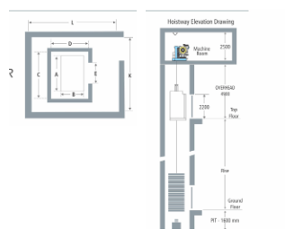
Architectural Legend (mm)
A:Platform Edge – width (car platform)
B:Platform Edge – depth (car platform)
C:Lift-Well In-Side Finished – width
D:Lift-Well In-Side Finished – depth
E:Entrance Width
K:Machine Room – width
L:Machine Room – length
Custom Shaft Geometry?Our CAD team provides bespoke GA layouts.
Call EngineerPassenger Elevator — Full Hoistway Dimensions & Specifications
Complete matrix covering both Automatic Center-Opening and Manual Door Passenger Elevator installations.
| Door System | Persons | Load (Kg) | Car Platform A × B (mm) | Lift-Well C × D (mm) | Entrance E (mm) | Door Type | Machine Room K × L (mm) | Speed (mps) | Pit (mm) | Overhead (mm) |
|---|---|---|---|---|---|---|---|---|---|---|
| Automatic Door | 6 | 408 | 1200 × 1300 | 1700 × 1800 | 700 | Auto Center Opening | 300+C+300 × 600+D+1500 | Up to 1.5 | 1600 | 4900 |
| Automatic Door | 8 | 544 | 1500 × 1330 | 2000 × 1800 | 800 | Auto Center Opening | 300+C+300 × 600+D+1500 | Up to 1.5 | 1600 | 4900 |
| Automatic Door | 10 | 680 | 1650 × 1450 | 2150 × 2000 | 800 | Auto Center Opening | 600+C+600 × 600+D+1500 | Up to 1.5 | 1600 | 4900 |
| Automatic Door | 13 | 884 | 1900 × 1500 | 2400 × 2000 | 800 | Auto Center Opening | 600+C+600 × 600+D+1500 | Up to 1.5 | 1600 | 4900 |
| Automatic Door | 16 | 1088 | 1900 × 1800 | 2400 × 2300 | 1000 | Auto Center Opening | 600+C+600 × 600+D+1500 | Up to 1.5 | 1600 | 4900 |
| Automatic Door | 20 | 1360 | 1900 × 2250 | 2400 × 2750 | 1000 | Auto Center Opening | 600+C+600 × 600+D+1500 | Up to 1.5 | 1600 | 4900 |
| Manual Door | 5 | 340 | 950 × 1300 | 1350 × 1650 | 760 | Collapsible Gate | 300+C+300 × 600+D+1500 | Up to 0.68 | 1600 | 4900 |
| Manual Door | 5 | 340 | 1300 × 1000 | 1700 × 1300 | 760 | Swing Door | 300+C+300 × 600+D+1500 | Up to 0.68 | 1600 | 4900 |
| Manual Door | 6 | 408 | 1200 × 1000 | 1600 × 1500 | 800 | Imperforate Gate | 300+C+300 × 600+D+1500 | Up to 0.68 | 1600 | 4900 |
| Manual Door | 8 | 544 | 1500 × 1200 | 1900 × 1500 | 800 | Collapsible / Swing | 300+C+300 × 600+D+1500 | Up to 0.68 | 1600 | 4900 |
| Manual Door | 13 | 884 | 1900 × 1500 | 2400 × 1850 | 900 | Collapsible / Swing | 600+C+600 × 300+D+1500 | Up to 0.68 | 1600 | 4900 |
| Manual Door | 16 | 1088 | 1900 × 1800 | 2400 × 2150 | 1000 | Collapsible / Swing | 600+C+600 × 300+D+1500 | Up to 0.68 | 1600 | 4900 |
| Manual Door | 20 | 1360 | 1900 × 2250 | 2400 × 2600 | 1000 | Collapsible / Swing | 600+C+600 × 300+D+1500 | Up to 0.68 | 1600 | 4900 |
•All Dimensions are in mm.
•All hoist way walls should be minimum 230 mm brick or 150 mm R.C.C.
•Standard engineering specifications. Custom dimensions available upon technical consultation.
Civil Engineering Pre-Requisites Checklist
Plumb Hoistway: True vertical plumb tolerance of ±25mm over entire building travel height.
Pit Waterproofing: 100% dry, water-tight pit with sump pit provision per municipal regulations.
Separator Beams: ISMB steel separator beams at every 2500 mm floor interval for multi-car shafts.
Machine Room Hook: Heavy-duty I-beam lifting hook tested to 2000 kg mounted in ceiling slab.